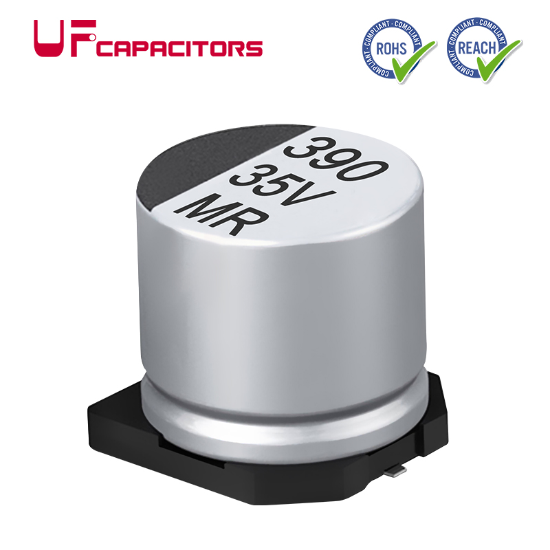
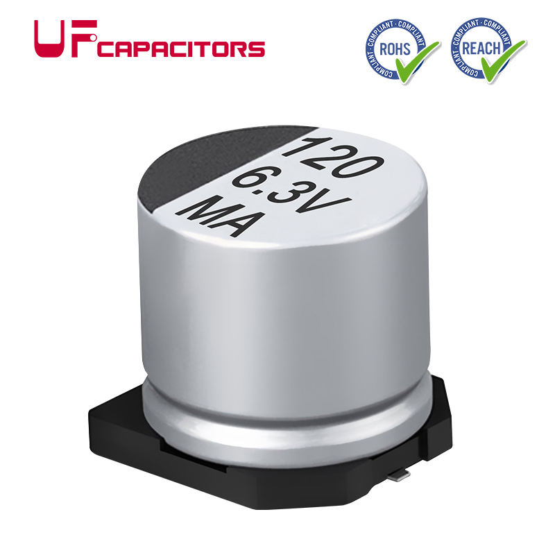
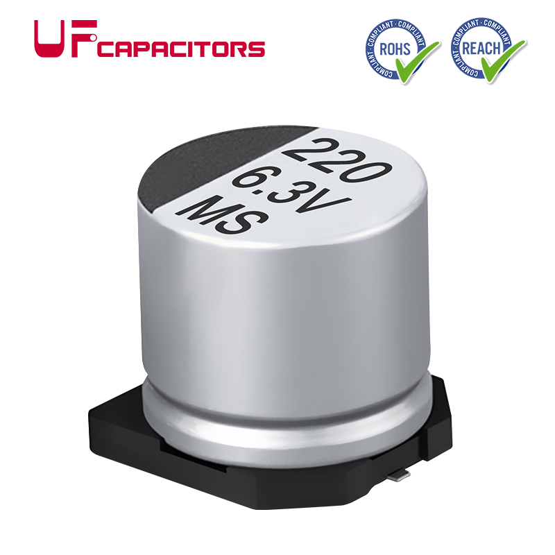
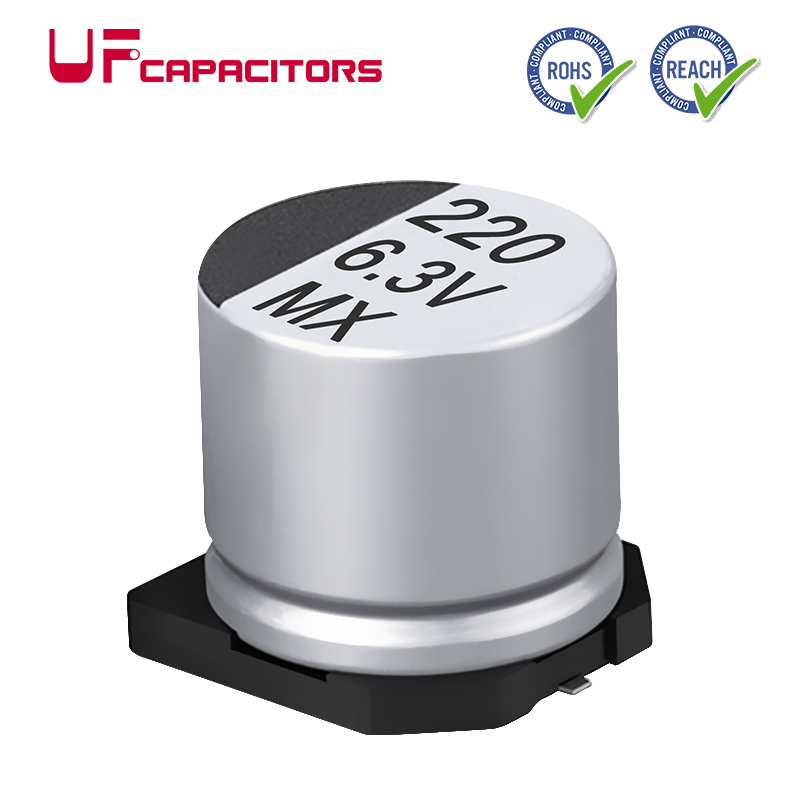
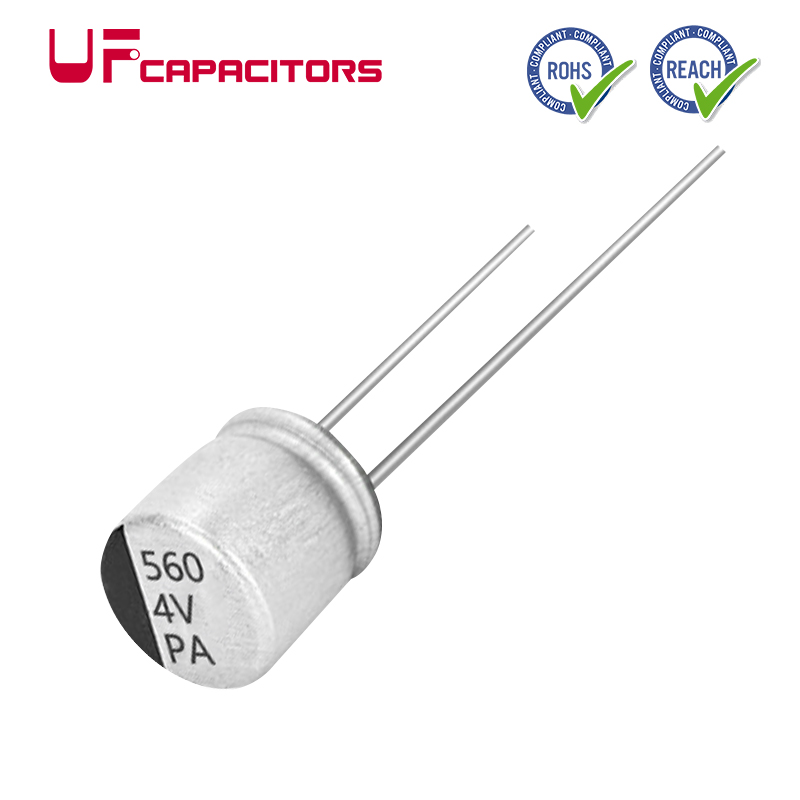
●CONDUCTIVE POLYMER HYBRID ALUMINUM ELECTROLYTIC CAPACITORS
TMR Series CHIP TYPE, HIGH RELIABILITY
UF Capacitors combine the benefits of Aluminum Electrolytic and Specialty Polymer Capacitors resulting in a Capacitor featuring high endurance, low-ESR, high tolerance for ripple current, inrush currents and elevated temperature. Hybrid Capacitors are known for their stable electric characteristics at high frequencies while maximizing reliability.
●TMR Series CHIP TYPE, HIGH RELIABILITY Introduction
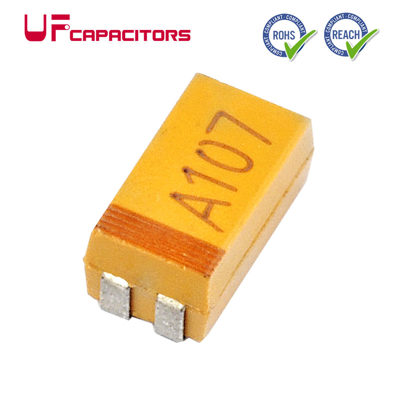
The TMR Series Conductive Polymer Hybrid Aluminum Capacitors are capable of operating at high temperatures with conductive Polymer Capacitor performance and Aluminum Electrolytic Capacitor safety in a Surface Mount package.
TheTMRSeries Hybrid Capacitors are ideal where high temperature and high current capability are in demand by the application and offer an extra-large capacitance at 125°C, 4000 hours.
●TMR Series CHIP TYPE, HIGH RELIABILITYFeatures
* Operating with wide temperature range -55~+125C
* High reliability & high voltage are realized by hybrid electrolyte
* Load life of 4000 hours
* RoHS & REACH compliant, Halogen-free
●TMR Series CHIP TYPE, HIGH RELIABILITY Application
* Typical applications include industrial power supplies
* Switch power supplies,
* Industrial control systems.
*Designed for surface mounting on high density circuit board.
●TMR Series CHIP TYPE, HIGH RELIABILITYDelivery, Shipping and Terms
4-6 Weeks Fast Delivery
Regular Stocks Available
Ex-work, FCA Terms, or FOB Terms
●TMR Series CHIP TYPE, HIGH RELIABILITYDrawing
|
Items
|
Characteristics
|
|
Operation Temperature Range
|
-55 ~ +125°C
|
|
Voltage Range
|
16 ~ 100V
|
|
Capacitance Range
|
22 ~ 1500μF
|
|
Capacitance Tolerance
|
±20% at 120Hz, 20°C
|
|
Leakage Current
|
Leakage current£0.01CV (after 2 minutes application of rated voltage at 20°C)C: Nominal capacitance (mF) , V: Rated voltage (V)
|
|
Dissipation Factor (tand)
|
£Specified value at 120Hz, 20°C.
|
|
ESR
|
£Specified value at 100KHz, 20°C.
|
|
Stability at Low Temperature
|
Measurement frequency : 100KHz
|
|
|
Impedance Ratio ZT/Z20 (max.)
|
Z(-25°C)/Z(20°C)
|
≤1.5
|
|
Z(-55°C)/Z(20°C)
|
≤2.0
|
|
Damp Heat (Steady State)
|
When the capacitors are restored to 20°C after the rated voltage is applied for 2000 hours at 85°C, 85% RH, they meet the characteristics listed below.
|
|
Capacitance Change
|
Within +/- 30% of initial value
|
|
Dissipation Factor
|
200% or less of initial specified value
|
|
ESR
|
200% or less of initial specified value
|
|
Leakage Current
|
Initial specified value or less
|
|
Endurance
|
After 4000 hours application of the rated voltage at 125°C, they meet the characteristics listed below.
|
|
Capacitance Change
|
Within +/- 30% of initial value
|
|
Dissipation Factor
|
200% or less of initial specified value
|
|
ESR
|
200% or less of initial specified value
|
|
Leakage Current
|
Initial specified value or less
|
|
Shelf Life
|
After leaving capacitors under no load at 125°C for 1000 hours, they meet the specified value for Endurance characteristics listed above.
|
|
Resistance to Soldering Heat
|
After reflow soldering and restored at room temperature, they meet the characteristics listed below.
|
|
Capacitance Change
|
Within +/-10% of initial value
|
|
Dissipation Factor
|
130% or less of initial specified value
|
|
ESR
|
130% or less of initial specified value
|
|
Leakage Current
|
Initial specified value or less
|
|
Marking
|
Red print on the case top.
|

●TMR Series CHIP TYPE, HIGH RELIABILITYDimensions
|
ÆD´L
|
6.3´6
|
6.3´7.7
|
8´10.5
|
8´12.5
|
10´10.5
|
10´12.5
|
|
A
|
7.3
|
7.3
|
9.0
|
9.0
|
11.0
|
11.0
|
|
B
|
6.6
|
6.6
|
8.3
|
8.3
|
10.3
|
10.3
|
|
C
|
6.6
|
6.6
|
8.3
|
8.3
|
10.3
|
10.3
|
|
E
|
1.9
|
1.9
|
3.1
|
3.1
|
4.7
|
4.7
|
|
L
|
6.0
|
7.7
|
10.5
|
12.5
|
10.5
|
12.5
|
|
H
|
0.5~0.8
|
0.5~0.8
|
0.8~1.1
|
0.8~1.1
|
0.8~1.1
|
0.8~1.1
|
DIMENSIONS & STANDARD RATINGS
WV (V)
Parameter
Cap.
(mF)
|
16
|
25
|
Case size
ÆD´L (mm)
|
Dissipation factor (tand)
|
Leakage current (mA)
|
ESR (mW)
max. 20°C, 100KHz
|
Ripple current (mA rms) 125°C,
100KHz
|
Case size
ÆD´L (mm)
|
Dissipation factor (tand)
|
Leakage current (mA)
|
ESR (mW)
max. 20°C, 100KHz
|
Ripple current (mA rms) 125°C,
100KHz
|
|
68
|
686
|
|
|
|
|
|
6.3 × 6.0
|
0.14
|
17
|
50
|
900
|
|
100
|
107
|
6.3 × 6.0
|
0.16
|
16
|
45
|
950
|
6.3 × 7.7
|
0.14
|
25
|
30
|
1400
|
|
150
|
157
|
|
|
|
|
|
6.3 × 7.7
|
0.14
|
37.5
|
30
|
1400
|
|
220
|
227
|
6.3 × 7.7
|
0.16
|
35.2
|
27
|
1450
|
8 × 10.5
|
0.14
|
67.5
|
27
|
1600
|
|
270
|
277
|
8 × 10.5
|
0.16
|
43.2
|
22
|
1700
|
|
|
|
|
|
|
330
|
337
|
|
|
|
|
|
8 × 10.5
(10 × 10.5)
|
0.14
(0.14)
|
82.5
(82.5)
|
27
(20)
|
1600
(2000)
|
|
470
|
477
|
8 × 10.5
(10 × 10.5)
|
0.16
(0.16)
|
75.2
(75.2)
|
22
(18)
|
1700
(2100)
|
8 × 12.5
(10 × 10.5)
|
0.14
(0.14)
|
117.5
(117.5)
|
23
(20)
|
1900
(2000)
|
|
680
|
687
|
|
|
|
|
|
10 × 12.5
|
0.14
|
170
|
15
|
2700
|
|
820
|
827
|
8 × 12.5
(10 × 10.5)
|
0.16
(0.16)
|
131.2
(131.2)
|
20
(18)
|
1850
(2100)
|
|
|
|
|
|
|
1500
|
158
|
10 × 12.5
|
0.16
|
240
|
14
|
3000
|
|
|
|
|
|
WV (V)
Parameter
Cap.
(mF)
|
35
|
50
|
Case size
ÆD´L (mm)
|
Dissipation factor (tand)
|
Leakage current (mA)
|
ESR (mW)
max. 20°C, 100KHz
|
Ripple current (mA rms) 125°C,
100KHz
|
Case size
ÆD´L (mm)
|
Dissipation factor (tand)
|
Leakage current (mA)
|
ESR (mW)
max. 20°C, 100KHz
|
Ripple current (mA rms) 125°C,
100KHz
|
|
27
|
276
|
|
|
|
|
|
6.3 × 6.0
|
0.10
|
13.5
|
80
|
750
|
|
33
|
336
|
|
|
|
|
|
6.3 × 7.7
|
0.10
|
16.5
|
40
|
1100
|
|
68
|
686
|
6.3 × 6.0
|
0.12
|
23.8
|
60
|
900
|
8 × 10.5
|
0.10
|
34
|
30
|
1250
|
|
100
|
107
|
6.3 × 7.7
|
0.12
|
35
|
35
|
1400
|
8 × 10.5
(10 × 10.5)
|
0.10
(0.10)
|
50
(50)
|
30
(25)
|
1150
(1600)
|
|
120
|
127
|
|
|
|
|
|
8 × 12.5
|
0.10
|
60
|
28
|
1400
|
|
150
|
157
|
8 × 10.5
|
0.12
|
52.5
|
27
|
1600
|
10 × 10.5
|
0.10
|
75
|
25
|
1600
|
|
180
|
187
|
8 × 10.5
|
0.12
|
63
|
27
|
1600
|
|
|
|
|
|
|
220
|
227
|
8 × 12.5
|
0.12
|
77
|
24
|
1800
|
10 × 12.5
|
0.12
|
110
|
23
|
1800
|
|
270
|
277
|
10 × 10.5
|
0.12
|
94.5
|
20
|
2000
|
|
|
|
|
|
|
330
|
337
|
10 × 10.5
|
0.12
|
115.5
|
20
|
2000
|
|
|
|
|
|
|
470
|
477
|
10 × 12.5
|
0.12
|
164.5
|
16
|
2600
|
|
|
|
|
|
WV (V)
Parameter
Cap.
(mF)
|
63
|
80
|
Case size
ÆD´L (mm)
|
Dissipation factor (tand)
|
Leakage current (mA)
|
ESR (mW)
max. 20°C, 100KHz
|
Ripple current (mA rms) 125°C,
100KHz
|
Case size
ÆD´L (mm)
|
Dissipation factor (tand)
|
Leakage current (mA)
|
ESR (mW)
max. 20°C, 100KHz
|
Ripple current (mA rms) 125°C,
100KHz
|
|
22
|
226
|
6.3 × 7.7
|
0.08
|
13.86
|
80
|
900
|
8 × 10.5
|
0.08
|
17.6
|
45
|
1050
|
|
33
|
336
|
8 × 10.5
|
0.08
|
20.79
|
40
|
1100
|
8 × 10.5
|
0.08
|
26.4
|
45
|
1050
|
|
47
|
476
|
8 × 10.5
|
0.08
|
29.61
|
40
|
1100
|
8 × 12.5
(10 × 10.5)
|
0.08
(0.08)
|
37.6
(37.6)
|
42
(36)
|
1200
(1200)
|
|
56
|
566
|
10 × 10.5
|
0.08
|
35.28
|
30
|
1400
|
10 × 10.5
|
0.08
|
44.8
|
36
|
1200
|
|
82
|
826
|
|
|
|
|
|
10 × 12.5
|
0.08
|
65.6
|
33
|
1350
|
|
100
|
107
|
8 × 10.5
(10 × 10.5)
|
0.08
(0.08)
|
63
(63)
|
36
(30)
|
1300
(1400)
|
|
|
|
|
|
|
150
|
157
|
10 × 12.5
|
0.08
|
94.5
|
26
|
1600
|
|
|
|
|
|
CONDUCTIVE POLYMER HYBRID ALUMINUM ELECTROLYTIC CAPACITORS
DIMENSIONS & STANDARD RATINGS
|
WV (V)
|
100
|
Parameter
Cap.
(mF)
|
Case size
ÆD´L (mm)
|
Dissipation factor (tand)
|
Leakage current (mA)
|
ESR (mW)
max. 20°C, 100KHz
|
Ripple current (mA rms) 125°C,
100KHz
|
|
33
|
336
|
10 × 10.5
|
0.08
|
33
|
80
|
850
|
|
47
|
476
|
10 × 12.5
|
0.08
|
47
|
60
|
1050
|
FREQUENCY COEFFICIENT OF ALLOWABLE RIPPLE CURRENT
|
Frequency
|
120Hz£f£1KHz
|
1KHz£f£10KHz
|
10KHz£f£100KHz
|
100KHz£f£300KHz
|
|
Coefficient
|
0.10
|
0.40
|
0.70
|
1.00
|
Note: Specification is subject to change without further notice. For more details and updates, please visit our website.


